
Design & Manufacturing

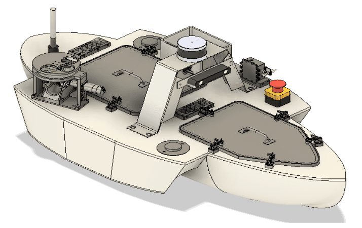
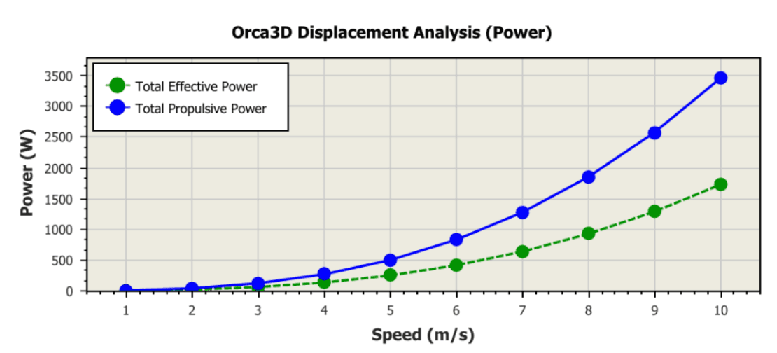
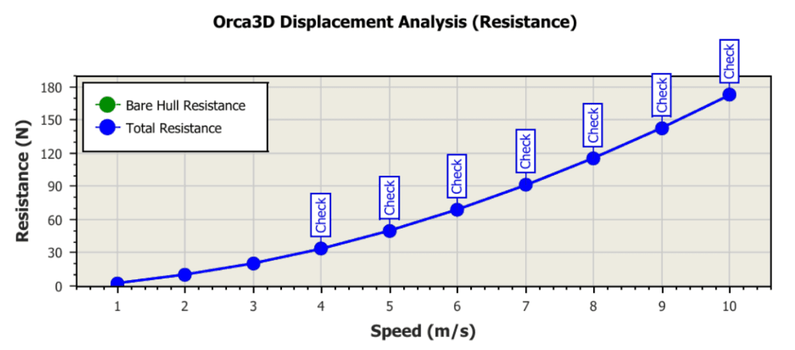
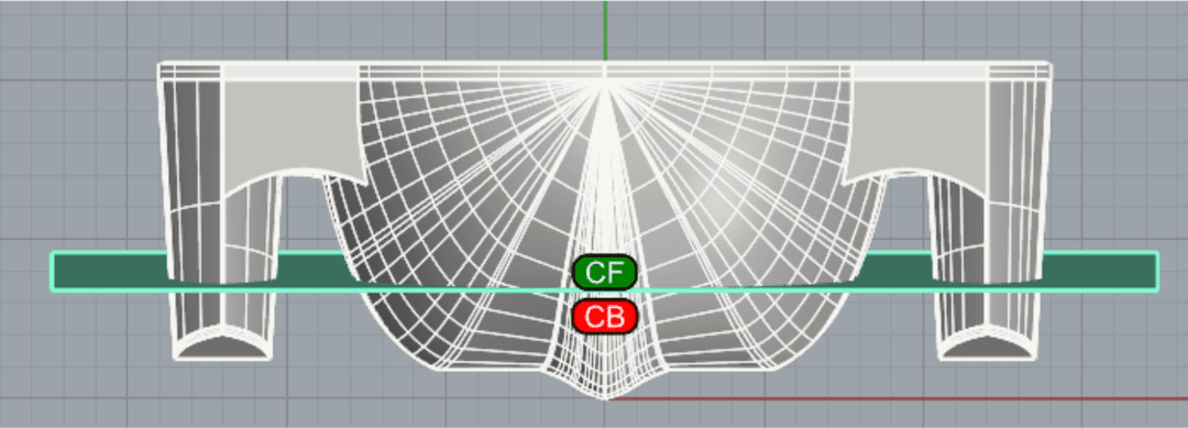
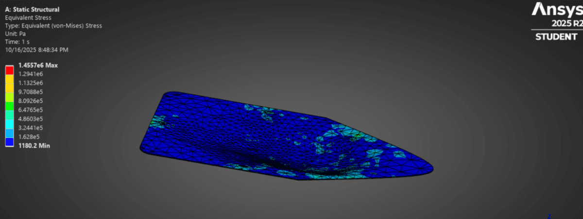
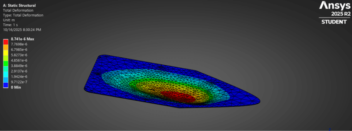
Our unique trimaran design has a hollow center hull that houses all the electronics, maximizing stability while minimizing weight. We leverage simulation tools like Ansys Fluent and Orca to optimize the boat’s performance on the water, ensuring stability, efficiency, and speed. Each structural component is designed with a high factor of safety for reliability. We employ Ansys static structural and modal analysis tools to verify our designs, followed by testing to validate their performance. The electronics bay is accessed through sealed openings, designed with redundancy, and tested for waterproofing. Most components are custom-made, utilizing a variety of techniques, including composite fabrication, machining, laser cutting, and 3D printing.
Our future goals include developing repeatable mold systems, fabricating forged composite parts, developing composite sandwiches with superior strength-to-weight ratios for the frame, and building a framework within LS-DYNA for crash simulations.
Hull Manufacturing
This year the amas and main hull were manufactured using a single, unified foam mold rather than being built separately. The mold was created from a combination of CNC-machined XPS foam and 3D printed elements to ensure symmetry and accuracy across the full assembly. After machining, the foam and 3D printed sections were adhered together and lightly sanded to achieve a smooth, continuous mold surface.
Because polyester resin cannot directly contact the foam, the entire mold was first covered in Tyvek tape, then coated with a thin, completely dried layer of epoxy fairing compound to create a smooth, stable base for the layup.
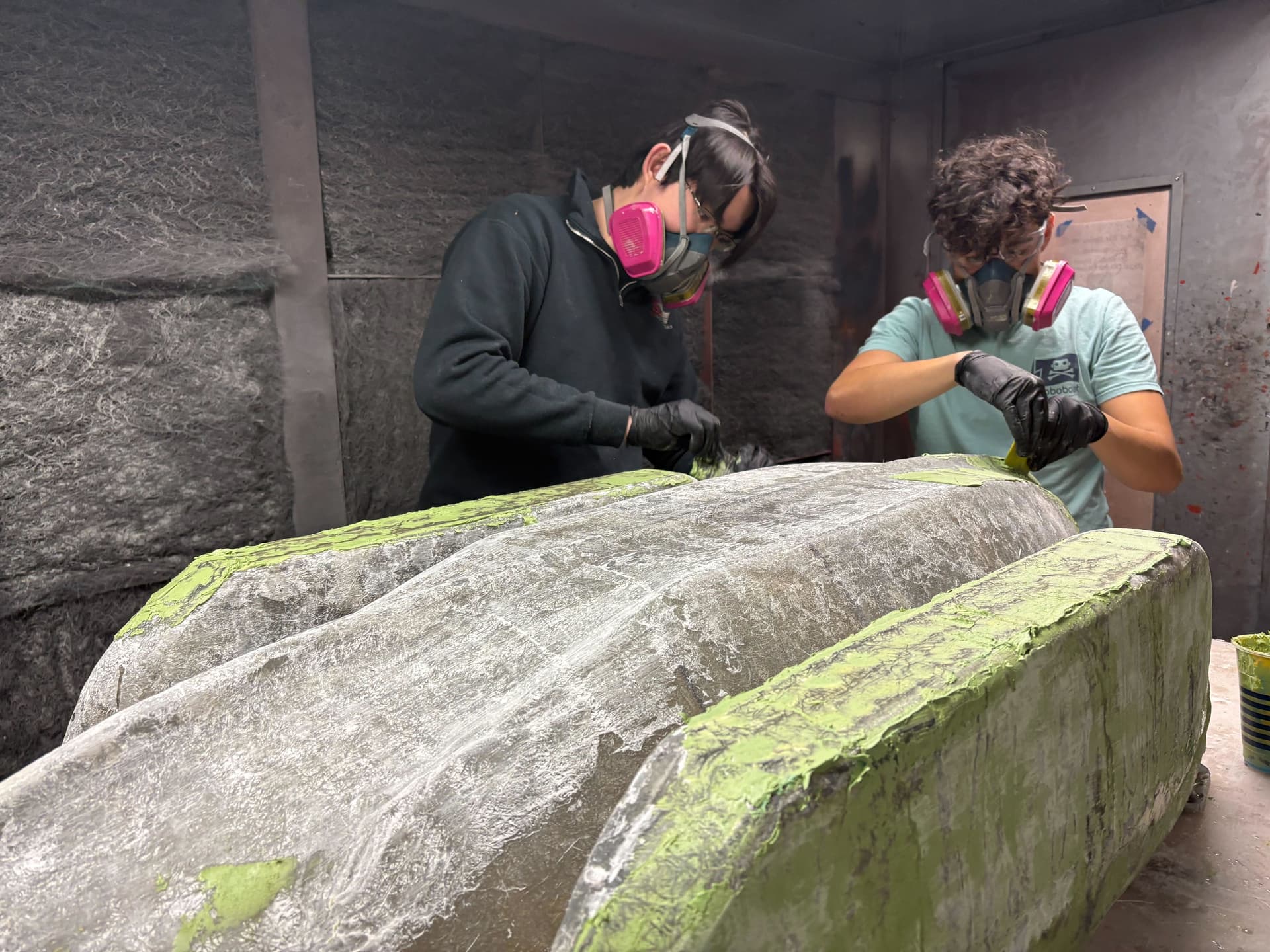
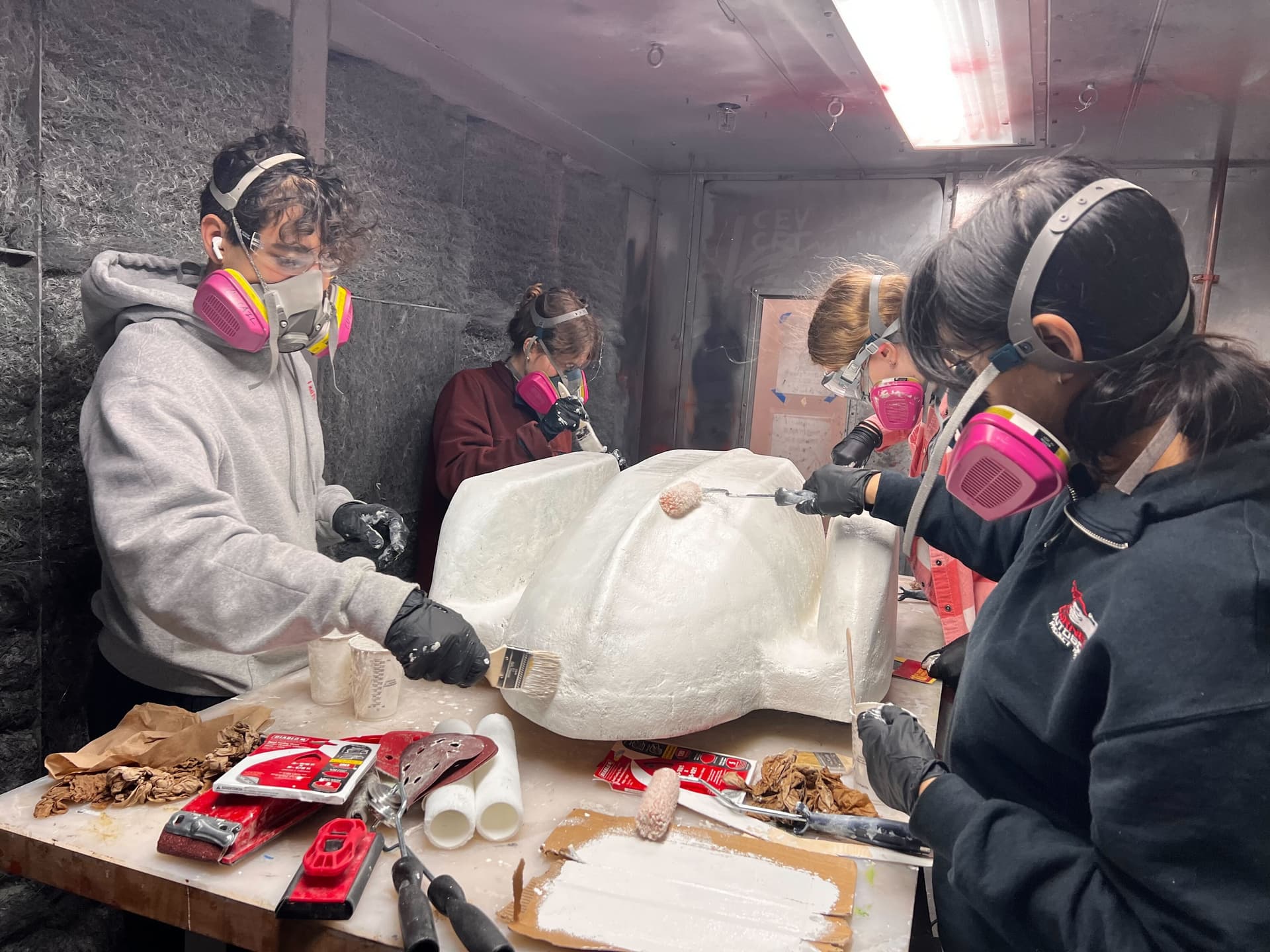
For the fiberglass layup, we used a Mat–Weave–Mat sandwich strategy. The chopped-strand mat on the inner and outer surfaces ensured smoothness and good resin wet-out, while the biaxial weave layer in the center provided most of the structural strength for both the ama sections and the main hull.
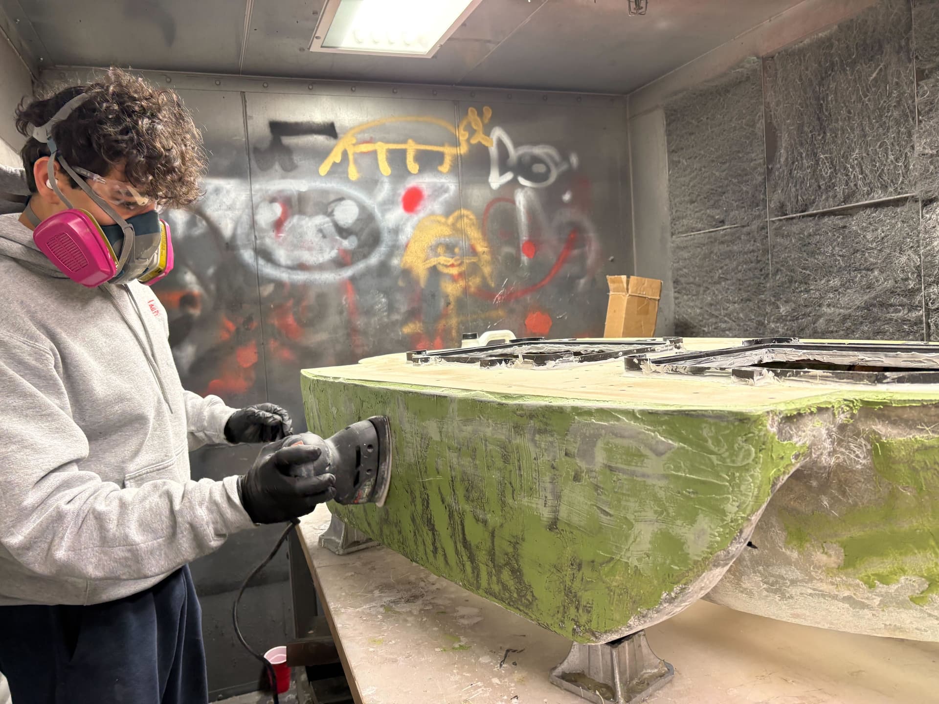
After curing, the composite surface was sanded, any small gaps were filled with fairing compound, and the hull was brought to a uniform smoothness. A barrier coat was then applied, followed by spray paint for appearance and UV protection.
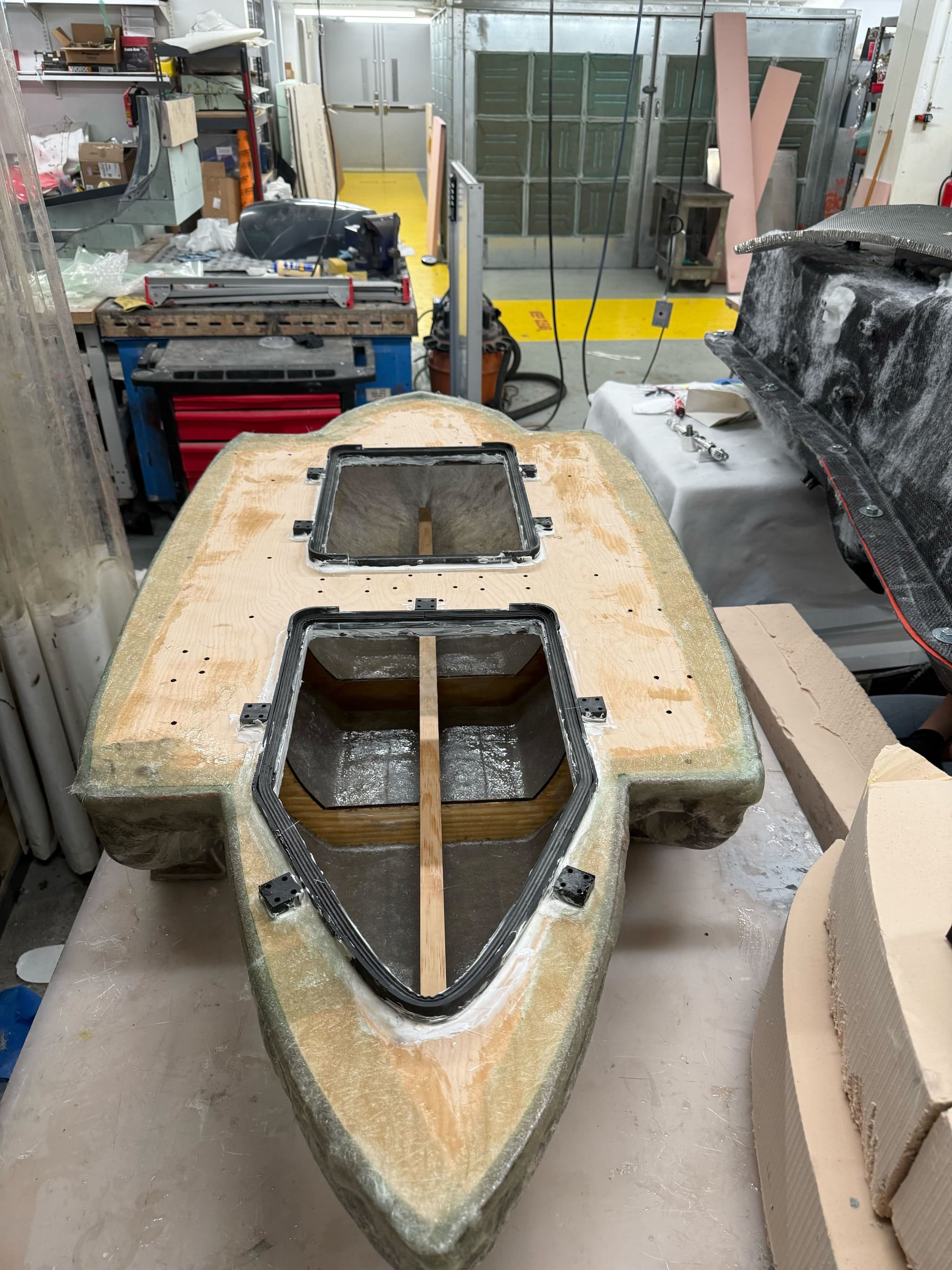
Internal Structure & Deck
After demolding, a wooden internal frame was installed. The frame consisted of laser-cut plywood ribs, a notched wooden beam for alignment, and a CNC-cut plywood deck with precise slots for each rib.
The wooden frame was glued together for strength and bonded inside the composite shell using fiberglass tabbing. After fitting the deck, the top edges of the hull were trimmed and sanded, and a final layer of chopped-strand mat fiberglass was added along the seam between the deck and hull to waterproof the joint.
Any final imperfections were faired and sanded, then the entire assembly received a protective barrier coat before being spray painted.
Testing
This semester we focused on evaluating both laminate strength and mold-release reliability. Several small test panels were produced to compare different fiberglass sequences, cure behavior, and surface quality. These tests helped us identify the Mat–Weave–Mat stack as the best balance of stiffness, durability, and workable thickness.
We also tested various mold-prep methods to ensure clean and consistent demolding from the foam mold. Trials using Tyvek tape, fairing compound, and different release layers allowed us to assess how easily panels separated after curing and how smooth the resulting surface was. These results guided the final mold-protection and layup approach used for the full-scale hull.